.png)
My Items
I'm a title. Click here to edit me.

A ghostly particle detected in Antarctica has led astronomers to a super-massive spinning black hole
Author: David Mosher Courtesy: Business Insider India Astronomers say they've more or less confirmed a key source of cosmic rays - some of the highest-energy yet most enigmatic radiation in the universe - with the detection of a single "ghostly" particle in Antarctica. Cosmic rays were discovered more than 100 years ago, but their origins are tough to know for sure because they can be deflected en route to Earth, and our planet's atmosphere absorbs most of them. Researchers detected the "ghost" particle, or neutrino, in September 2017 using IceCube, a huge array of sensors embedded deep in the ice of Antarctica. The neutrino was unusually energetic, and when scientists tracked the particle back to its source, they found a galactic monster called a blazar: a rapidly spinning black hole millions of times the mass of the sun that's gobbling up gas and dust. The blazar is called TXS 0506+056, and it appears in the sky just below the arm of the constellation Orion. The supermassive black hole is located 4 billion light-years away from Earth, in the core of what's called an active galaxy. IceCube/NASA/NSF
The location (green target) of blazar TXS 0506+056 in the arm of the constellation Orion.
After the high-energy neutrino's detection, IceCube alerted other astronomers, who aimed a suite of light-based observatories at the blazar. Those telescopes and detectors captured a massive burst of other radiation. "This is the first evidence that we have of an active galaxy emitting neutrinos, which means we may soon start observing the universe using neutrinos to learn more about these objects in ways that would be impossible with light alone," Marcos Santander, an astrophysicist at the University of Alabama, said in a press release. Santander and dozens of others have detailed their research in two studies published in the journal Science. The first study links the high-energy neutrino - which researchers believe was generated by cosmic rays - to the blazar. A second study shores up more evidence for the link by finding many more lower-energy neutrinos apparently emanating from the blazar. Erin Bonning, an astrophysicist at Emory University who studied blazars and wasn't involved in the research, said the work - if the statistical details bear out - is "really cool" because it's only the second time that a high-energy neutrino has been linked to source outside our solar system. The first was a couple dozen neutrinos emitted by a supernova in 1987. Blazars represent a potentially large source of cosmic rays, since there are hundreds of billions of galaxies in the visible universe, and about 10% at any time are "active," meaning they're eating matter. Feeding black holes shoot out jets of high-energy radiation and particles at close to the speed of light. "The thing that makes a blazar different from an active galactic nuclei is that a blazar is when Earth is looking down the barrel of a jet," Bonning said. The grand mystery - and importance - of cosmic rays Cosmic rays constantly bombard the Earth. Also called cosmic ionizing radiation, the particles are the cores of atoms or subatomic pieces of their cores, called protons, moving at nearly light-speed. They can travel for billions of years through space before randomly hitting Earth. You can't see these high-energy charged particles, but at any given moment, tens of thousands of them are soaring through space and slamming into Earth's atmosphere from all directions. These rays don't pose much risk to humans on Earth's surface, since the planet's atmosphere and magnetic field shield us from most of the threat. "Cosmic rays are not a significant exposure risk on the ground," Eddie Semones, a radiation health officer at NASA, previously told Business Insider. "You actually get more exposure from the Earth's natural radioactive material than from galactic cosmic rays." But far above the ground, where air is less dense, the particles are more likely to affect people. That's why flight attendants, pilots, and deep-space astronauts face a higher risk of cancers. Many cosmic rays appear to come from exploding stars called supernovas, though their exact contribution to the total amount of the radiation, or flux, is not certain. The two new studies show that blazars appear to be an important source of cosmic rays - some of the highest-energy ones around. Bonning said making that connection is important, though not unexpected. "The physics behind blazars producing cosmic rays is not controversial," she said. "It's generally accepted these are the types of sources that can produce cosmic rays." But researchers have struggled so long to make such links because all of the stuff in the universe - especially magnetic objects, gas, and dust - can mess with the path of cosmic rays on their journey to Earth. "You can see a cosmic ray coming from over there, but that doesn't necessarily mean it came from that way," Bonning said. "They can spiral around." That's where neutrinos come in: trillions from the sun pass through the palm of your hand in one second, since they ignore nearly all other stuff in the universe. IceCube does not detect neutrinos directly, but instead records their rare interactions with molecules. Every now then, after trillions and trillions of neutrinos pass by uninhibited, one will occasionally whack into a large particle and propel it faster than the speed of light. This is possible because light travels more slowly through ice. However, when that universal speed limit is broken by particles of matter, they shed a bunch of photons (particles of light) in response. An array of photon detectors in ice can thus help scientists rebuild the path of a neutrino by looking at sequences of how they were set off. Bonning says researchers outside the IceCube Collaboration, and other teams involved in the work, will likely question the strength of the connection due to the statistics: Both studies are based on the detection of a single neutrino. "The probability of this being chance is 1 in 1,000, or what scientists call 3-sigma," Bonning said, adding: "This is the bare minimum to claim you've detected something." She said the second study bolsters the work, since it compares previous light-based observations of blazar TXS 0506+056 when it was feeding with lower-energy neutrinos detected by IceCube. That study found the same blazar to be the source with a better-than-1-in-1,000 chance. Bonning said that, beyond the possible confirmation of blazars as a source of high-energy cosmic rays, the studies open the door a bit farther to using neutrinos as telescopes for objects beyond our solar system. That's important because we still know so little about distant galaxies, let alone cosmic rays. "Like the detection of gravitational waves, it's the beginning of some new discoveries," she said. "Over time, they'll be able to correlate other neutrinos with similar objects."

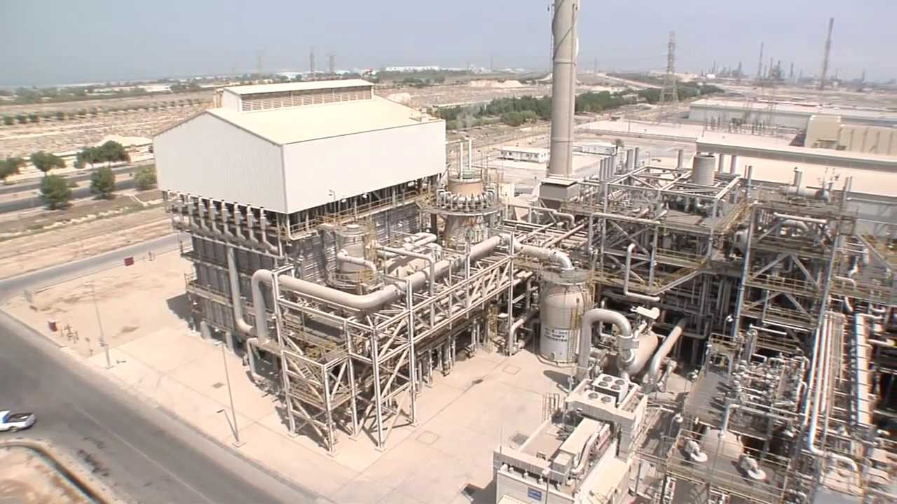
High temperature and hydrogen induced material Degradation and aging in Chemical Industries
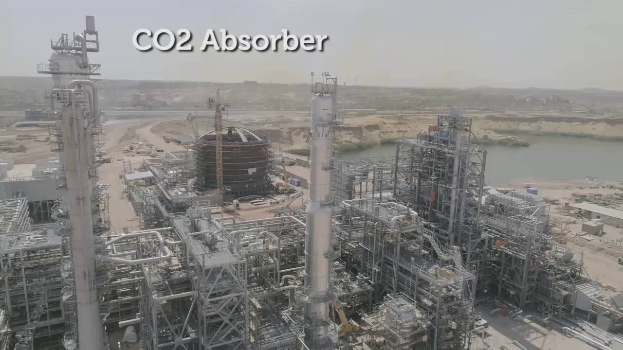
(Full Article with concluding part) Introduction Chemical plants like natural gas-based fertilizer industries operating at high temperature and handling corrosive and hazardous substances at higher pressure are subjected to ageing and its equipment and piping tend to degrade over time. There are many areas which are prone to aging but can go unnoticed, leading to safety hazards for the plant and people. Replacement of whole plant and even sub-systems are not always economically feasible which give rise to the need of assessment of systems and its components for risk associated with failure. With a view to assess the same, it calls for understanding the mechanism of degradation so that remaining life assessment of equipment can be carried out more precisely. Degradation Mechanism Materials degrades with passage of time due to many factors, out of which following major mechanisms are creep, microstructural degradation, high temperature fatigue, carburization, hydrogen damage and embrittlement, graphitization, thermal shock, liquid erosion, dual phase erosion, corrosion, erosion-corrosion mechanism, liquid metal embrittlement, Stress corrosion cracking, caustic gauging, metal dusting etc. Creep Equipment and piping under high temperature and stress are subjected to progressive degradation called creep. Creep is one of the most important degradation mechanisms which involves time-dependent deformation which can lead to rupture of the material. The failure of materials by creep damage depends on temperature and the extent of stress the material is subjected to. The degradation once starts gradually progresses and develops microcracks and propagates through grain boundaries leading to rupture. High temperature equipment like catalyst tube in fired furnace, Boiler, tubes and headers in steam superheater, piping inside waste heat section of duct, tubes in BFW preheater, reactor, catalyst basket screen of Ammonia reactor, tubes TTS weld of heat exchangers handling hot process gas, intercoolers in syn gas compressor system, gas turbine components etc. are always subjected to continuous exposure of high temperature where stresses like internal pressure centrifugal force, static load are associated causing the combine degradation of creep. At higher temperatures, creep can occur uniformly or with localized deformation having symptoms of large plastic strains, local wall thinning, elongation etc. The combination of lower and higher temp and stresses at higher or lower level produces different types of fractures and characterization of this cracks under various conditions can be known from characteristic map developed by Ashby, Mohamed and Langdon. Qualitative approach of evaluating defects like creep void, microcracks can be done with Neubauer and Wedel based model. This model helps understand damage stages in high temperature steam network with the help of in-situ metallography. Collecting replica in in-situ metallography is easy method with damaging the component, but not suitable for many metals like some Cr-Mo steel, where voids may get created during polishing and etching. The degree of spheroidization of carbides in bainitic and pearlitic structure tells about extent of thermal exposure and consequential damage. Sometime, measurement of hardness is required to substantiate loss of tensile strength and assessment of remaining life in material under creep damage mechanism. Microstructural degradation This type of damage mechanism is caused by other damaging processes like creep, for which continual degradation in metallographic structures are seen. Most predominantly the metal structures with grains gradually degraded with precipitation in grain boundary, developing micro cracks and sometimes trans-granular cracks are being propagated leading failure. Spherodization: This is the aging phenomena, when certain type of carbon steel and low alloy steel are subjected to a specific range of temp (440 degC to 760deg C), carbide phases become unstable and start to form cluster resulting in loss of strength. The higher the temp close to higher end the degradation is faster even can happen in hours, however the process significantly slows down with the fall in temperature. Although, the threat to failure due to spherodization is quite less, except for a few pressure vessels or piping operating in the susceptible temperature range or in a fired furnace where conditions tend to fluctuate widely which may include furnace catalyst tubes, exothermic reactors (e.g. Ammonia converter), and other pressure vessel with fluctuating operating temperatures which are exposed to uncontrolled exothermic reaction with possibilities of runaway reaction. Designing these pressure vessels and choosing the materials for construction is tricky thing; as some steels are more susceptible to this degradation, including fine-grained normalized steels. Therefore, choosing the correct ASTM grain size range is key factor for ensuring long life of the components. Likelihood of spheroidization damage can be evaluated with standard hardness testing and can be confirmed by metallography. Softening and Decarburization It is process of depleting carbons in carbon and low alloy steel when subjected to high temperatures in a oxidizing or reducing environment. It generally happens metals are heated beyond 700 deg C when the metal reacts with gases containing oxygen and hydrogen. The carbons which resides in the form of metal carbides, gets removed in the form of CO, CO2 or CH4. The depletion of carbon results in softening of metal, primarily on the external surface where decarburizing gas reacts with metal. The steps of decarburization mechanism can be three distinct events: the reaction at the steel surface, the interstitial diffusion of carbon atoms and the disbanding of carbides within the steel. Decarburization can be utilized for softening of metal where it is desired. Embrittlement and carburization This phenomenon is reverse of Softening and decarburization as described above. This can happen in several different ways. Austenitic stainless steels: Sigma phase formation in high temperature or in critical temperature range (approximately 565 to 980 °C) which causes loss of ductility and induce embrittlement. Ferritic stainless steels: Embrittlement is observed when held at or cooled over in the temperature range 550 to 400 °C. If service conditions are close to this temperature range, metallographic checks are recommended after extended exposure to avoid unexpected rupture. In addition to the embrittlement, carburization can lead to brittle structure it is exposed to a high temperature carburizing atmosphere for long time. Fig D shows extensive carbide formation in grain boundary of SS321 pipe in flue gas service. Hydrogen damage can occur in carbon steels under hydrogen atmosphere particularly in high temp and pressure, results in diffusion of atomic hydrogen to form methane reacting with carbon present in iron carbide. Hydrogen damage or embrittlement can be categorized into two broad categories HAC (hydrogen assisted cracking) and HIC hydrogen induced cracking. It has been revealed that steels with lower UTS (less than 140KSI) or hardness less than 32 HRC are not susceptible to hydrogen embrittlement phenomenon. Steels like precipitation hardened steel (like 17-4PH) severe loss of ductility is observed when exposed high pressure hydrogen. Hydrogen damages are most common in carbon steel, aluminium and titanium, however austempered steels are resistant to embrittlement caused by hydrogen. Austenitic stainless steel, High nickel alloys, beryllium copper are ale resistant to hydrogen embrittlement. The following three parameters are considered responsible for hydrogen damage: Presence and partial pressure of hydrogen a susceptible material Pressure or stress Temperature When assisted by a concentration gradient where there is significantly more hydrogen outside the metal than inside, hydrogen diffusion can occur even at lower temperatures. Hydrogen damage mechanism is consisting of following: Internal pressure within the metal: Hydrogen atoms get absorbed in surface and get diffused and may recombine to form hydrogen molecules creating pressure within the metal. This pressure ultimately led to opening of cracks when metal lose ductility and toughness. (HIC)
Metal hydride formation: Hydrogen reacts with metal to form brittle hydrides which allows cracks to propagate. Hydrogen enhanced decohesion: Hydrogen can induce decohesion where the strength of the atomic bonds of the parent material are reduced. Hydrogen enhanced localized plasticity (HELP): The mechanism of HELP was first proposed by C. Beachem. The process illustrates enhancement of mobility of dislocations in the presence of hydrogen atoms, results in propagation of defects /cracks even at lower stresses required. Hydrogen enhanced dislocation emission: This process tells about the enhancement of dislocation due to adsorption of hydrogen onto metal surface. Hydrogen enhances the mobility of dislocations in FCC, BCC and HCP ordered and disordered materials. It occurs for all dislocation types including partial and perfect lattice dislocations and grain boundary dislocations. Graphitization: The process of microstructural degradation takes place in ferritic steels if is exposed to high temperature for long time. Since graphite phase is more stable the phases gradually change from cementite to pearlite and ultimately to graphite. During the service graphite particles tend to align and form the crack. With the development of Cr-Mo Steel this degradation could be avoided. Thermal shock Thermal shock is associated with rapid changes in temperature due to external and internal reasons. As result of steep temperature gradient, thermal fatigue is produced to initiate grain separation leading to generation of crack and further propagation. Such problems are being faced in chemical, refineries, thermal power, and fertilizer plant, wherein situation may arise due to process emergencies and run-away reaction in reactors in presence of catalyst. Failures are generally happened in brittle materials particularly in cast grade materials. Catalyst tubes which face extreme heat from radiant burner is susceptible to such type of failure. (Crack getting initiated due to thermal shock, image source www.reasearchgate.net) Prevention of such failure mechanism is adhering to manufacturing protocol or if there in nothing available, 20 to 30 deg C per hour heating and cooling rate is considered safe to avoid thermal shock in any component subjected to extreme heat. Erosion Erosion happens when fluid contains liquid or solid suspended particles. These particles cause scratch on fluid contact surface, particularly when flow velocity is higher. This is abundantly happening in flue gas containing fly-ash and other dusts leading to heat transfer tubes in boilers. When fluid reached to dual phases (like saturated steam), some water droplets are formed inside the steam piping causing erosion in piping and turbine blades. Thinning of components pose a great safety hazard as sometimes thickness of the pipe wall is very difficult to measure due to heat and when it happens in localized part. (Erosion in boiler tube, source:www.davidnfrench.com) The control of this erosion depends on content of particles in the fluid and velocity of it. The usual solution to decrease the flow velocity is by increasing the pipe size. Usually, installation of strainer is not feasible if particle size distribution is mostly submicronic. However, water droplets cannot addressed by effective use of impingement and coalescent type filter. The solution to fly ash erosion can be performed by improving boiler flue gas distribution, and further reducing high gas velocities. Liquid metal embrittlement (LME) Liquid metal embrittlement is a corrosion mechanism which can occur in a number of combinations of liquid, solid and metal. We have noticed a very serious consequences prevalent in fertilizer, chemical and refineries is LME of austenitic stainless steel in presence of zinc. In addition to above, it can happen in several metal embrittling couples. The possible occurrence of liquid metal embrittlement might be due to following: Less or negligible solubility between the solid metals and interacting liquid. No formation of intermetallic compound between the solid-liquid couple. In 1975, the disastrous explosion at a plant in UK killed 28 people. The cause of failure was attributed to liquid metal embrittlement of a stainless-steel pipe in contact with molten zinc. Steels get embrittled by zinc in more than 400°C temperature. If stresses are present, it leads to fast rates of crack propagation. Nickel alloys get embrittled by zinc, Mercury or bismuth, but to a lesser extent than carbon and stainless steels. The presence of stress and higher temperature compound the effect on the severity of liquid metal embrittlement. The classic example of liquid copper metal embrittlement of steel is shown in figure below where the Cu has penetrated along the austenite grain boundaries when the carbon steel was at a temperature of 1100 °C. Cracking can be extremely rapid (>=0.05 m/s) and stress levels can be as low as 20 MPa for such cracking to take place. Two types of embrittlement attack are thought to occur in austenitic stainless steel in presence if zinc. Type 1 embrittlement is a relatively slow process, which depends on diffusion along austenite grain boundaries, which have Ni-depleted zones along it. The FCC austenite structure turns into to BCC ferrite, creating stress due to expansion leading to cracking. Type 2 embrittlement occurs at a much faster rate than type-1. This requires an external stress to initiate crack. Protective layer of oxide film prevent such cracking unless it has local defects. LME Couples There are a specific liquid metals combinations called as LME couples which leads to catastrophic intergranular cracking. For example, carbon steels are susceptible to LME by copper. Stainless steels are susceptible to LME by zinc respectively. Nickel and its high alloys are affected by Bismuth. Aluminum is susceptible to LME by mercury and gallium. Copper and its alloys are susceptible to liquid metal cracking by mercury and lithium. Cracking usually propagates in rapid pace, at a rate of 5-25 cm/s. Sulfidation-oxidation in Austenitic Stainless steel Sulfidation corrosion in elevated temperature is one of the most well-known damage mechanisms in chemicals and oil refining industry. It is prevalent in refinery industries as it has natural presence in fossil fuel. The corrosion can lead to thinning of pressure parts, like piping walls, shell wall of container and pressure vessels. Sulfidation depends on many factors, such as sulfur content, service temperatures, presence of erosion mechanism like high flow, and H2 concentration. This type of corrosion in high temperature is prevalent in super-heaters, coal gasification systems, Naptha or NG heater, gas turbines and fired furnaces. Sulfidation affects in two distinct mechanisms: Condition where H2 is present in addition to sulfur, such as hydro-cracking. Hydrogen free atmosphere in processing units. However, both the mechanisms are diffusion-based that occur at elevated temperature. Sulfidation in Hydrogen-Hydrogen Sulphide Environments: The mechanism of Corrosion Iron Sulphide scales are essentially formed in both the mechanisms, i.e. hydrogen free as well as H2-H2S environment. Cr alloy has shown better corrosion resistance in Hydrogen free environment than most of other steels, however, in H2-H2S environment, the resistance is only slightly better than carbon steel. It is presumed that in presence of hydrogen sulphur or its compound forms H2S in elevated temperature and if H2S concentration is more corrosion rate is observed higher. In Hydrogen free corrosion mechanism follows four steps: (1) Adsorption of the sulfur compounds. (2) Catalyzed decomposition of the sulfur compounds leading cation vacancies. (3) Migration and diffusion of cation vacancies to the FeSx/Fe interface. (4) Fe getting oxidized to form scale reduction of of cation vacancies. As per API 571 a threshold of 500 °F (260 °C) is considered for hydrogen-free services while in H2-environment the threshold temperature is considered at 450 °F (230 °C). Rapid degradation takes place when oxygen partial pressure is low in gas mixture. It is because protective layer of Cr2 O3 is inadequately form on exposed surface. Under this condition sulfidation corrosion are very rapid. Ref: Sciencedirect.com, http://www.researchgate.net, http://www.inspectionengineering.com, https://www.corrosionclinic.com/ https://inspectioneering.com/ DISLOCATION MOBILITY AND HYDROGEN – A BRIEF REVIEW by I. M. Robertson and H. K. Birnbaum (University of Illinois) Image courtesy: Machinedesign.com

High temperature and hydrogen induced material Degradation and aging in Chemical Industries
Introduction Chemical plants like natural gas-based fertilizer industries operating at high temperature and handling corrosive and hazardous substances at higher pressure are subjected to ageing and its equipment and piping tend to degrade over time. There are many areas which are prone to aging but can go unnoticed, leading to safety hazards for the plant and people. Replacement of whole plant and even sub-systems are not always economically feasible which give rise to the need of assessment of systems and its components for risk associated with failure. With a view to assess the same, it calls for understanding the mechanism of degradation so that remaining life assessment of equipment can be carried out more precisely. Degradation Mechanism Materials degrades with passage of time due to many factors, out of which following major mechanisms are creep, microstructural degradation, high temperature fatigue, carburization, hydrogen damage and embrittlement, graphitization, thermal shock, liquid erosion, dual phase erosion, corrosion, erosion-corrosion mechanism, liquid metal embrittlement, Stress corrosion cracking, caustic gauging, metal dusting etc Creep Equipment and piping under high temperature and stress are subjected to progressive degradation called creep. Creep is one of the most important degradation mechanisms which involves time-dependent deformation which can lead to rupture of the material. The failure of materials by creep damage depends on temperature and the extent of stress the material is subjected to. The degradation once starts gradually progresses and develops microcracks and propagates through grain boundaries leading to rupture. High temperature equipment like catalyst tube in fired furnace, Boiler, tubes and headers in steam superheater, piping inside waste heat section of duct, tubes in BFW preheater, reactor, catalyst basket screen of Ammonia reactor, tubes TTS weld of heat exchangers handling hot process gas, intercoolers in syn gas compressor system, gas turbine components etc are always subjected to continuous exposure of high temperature where stresses like internal pressure centrifugal force, static load are associated causing the combine degradation of creep. Fig-1: Stages of damage by creep At higher temperatures, creep can occur uniformly or with localized deformation having symptoms of large plastic strains, local wall thinning, elongation etc. The combination of lower and higher temp and stresses at higher or lower level produces different types of fractures and characterization of this cracks under various conditions can be known from characteristic map developed by Ashby, Mohamed and Langdon. Qualitative approach of evaluating defects like creep void, microcracks can be done with Neubauer and Wedel based model. This model helps understand damage stages in high temperature steam network with the help of in-situ metallography. Collecting replica in in-situ metallography is easy method with damaging the component, but not suitable for many metals like some Cr-Mo steel, where voids may get created during polishing and etching. The degree of spheroidization of carbides in bainitic and pearlitic structure tells about extent of thermal exposure and consequential damage. Sometime, measurement of hardness is required to substantiate loss of tensile strength and assessment of remaining life in material under creep damage mechanism. Microstructural degradation This type of damage mechanism is caused by other damaging processes like creep, for which continual degradation in metallographic structures are seen. Most predominantly the metal structures with grains gradually degraded with precipitation in grain boundary, developing micro cracks and sometimes trans-granular cracks are being propagated leading failure. Spherodization: This is the aging phenomena, when certain type of carbon steel and low alloy steel are subjected to a specific range of temp (440 degC to 760deg C), carbide phases become unstable and start to form cluster resulting in loss of strength. The higher the temp close to higher end the degradation is faster even can happen in hours, however the process significantly slows down with the fall in temperature. Although, the threat to failure due to spherodization is quite less, except for a few pressure vessels or piping operating in the susceptible temperature range or in a fired furnace where conditions tend to fluctuate widely which may include furnace catalyst tubes, exothermic reactors (e.g. Ammonia converter), and other pressure vessel with fluctuating operating temperatures which are exposed to uncontrolled exothermic reaction with possibilities of runaway reaction. Designing these pressure vessels and choosing the materials for construction is tricky thing; as some steels are more susceptible to this degradation, including fine-grained normalized steels. Therefore, choosing the correct ASTM grain size range is key factor for ensuring long life of the components. Likelihood of spheroidization damage can be evaluated with standard hardness testing and can be confirmed by metallography. Softening and Decarburization It is process of depleting carbons in carbon and low alloy steel when subjected to high temperatures in a oxidizing or reducing environment. It generally happens metals are heated beyond 700 deg C when the metal reacts with gases containing oxygen and hydrogen. The carbons which resides in the form of metal carbides, gets removed in the form of CO, CO2 or CH4. The depletion of carbon results in softening of matal, primarily on the external surface where decarburizing gas reacts with metal. The steps of decarburization mechanism can be three distinct events: the reaction at the steel surface, the interstitial diffusion of carbon atoms and the disbanding of carbides within the steel. Decarburization can be utilized for softening of metal where it is desired. Embrittlement and carburization This phenomenon is reverse of Softening and decarburization as described above. This can happen in several different ways. Austenitic stainless steels: Sigma phase formation in high temperature or in critical temperature range (approximately 565 to 980 °C) which causes loss of ductility and induce embrittlement. Ferritic stainless steels: Embrittlement is observed when held at or cooled over in the temperature range 550 to 400 °C. If service conditions are close to this temperature range, metallographic checks are recommended after extended exposure to avoid unexpected rupture. In addition to the embrittlement, carburization can lead to brittle structure it is exposed to a high temperature carburizing atmosphere for long time. Fig2 . shows extensive carbide formation in grain boundary of SS321 pipe in flue gas service. Hydrogen damage can occur in carbon steels under hydrogen atmosphere particularly in high temp and pressure, results in diffusion of atomic hydrogen to form methane reacting with carbon present in iron carbide. Hydrogen damage or embrittlement can be categorized into two broad categories HAC (hydrogen assisted cracking) and HIC hydrogen induced cracking. It has been revealed that steels with lower UTS (less than 140KSI) or hardness less than 32 HRC are not susceptible to hydrogen embrittlement phenomenon. Steels like precipitation hardened steel (like 17-4PH) severe loss of ductility is observed when exposed high pressure hydrogen. Hydrogen damages are most common in carbon steel, aluminium and titanium, however austempered steels are resistant to embrittlement caused by hydrogen. Austenitic stainless steel, High nickel alloys, beryllium copper are ale resistant to hydrogen embrittlement. The following three parameters are considered responsible for hydrogen damage: Presence and partial pressure of hydrogen Susceptible material Pressure or stress Temperature When assisted by a concentration gradient where there is significantly more hydrogen outside the metal than inside, hydrogen diffusion can occur even at lower temperatures. Hydrogen damage mechanism is consisting of following: Internal pressure within the metal: Hydrogen atoms get absorbed in surface and get diffused and may recombine to form hydrogen molecules creating pressure within the metal. This pressure ultimately led to opening of cracks when metal lose ductility and toughness. (HIC)
Metal hydride formation: Hydrogen reacts with metal to form brittle hydrides which allows cracks to propagate. Hydrogen enhanced decohesion: Hydrogen can induce decohesion where the strength of the atomic bonds of the parent material are reduced. Hydrogen enhanced localised plasticity (HELP): The mechanism of HELP was first proposed by C. Beachem. The process illustrates enhancement of mobility of dislocations in the presence of hydrogen atoms, results in propagation of defects /cracks even at lower stresses required. Hydrogen enhanced dislocation emission: This process tells about the enhancement of dislocation due to adsorption of hydrogen onto metal surface. Hydrogen enhances the mobility of dislocations in FCC, BCC and HCP ordered and disordered materials. It occurs for all dislocation types including partial and perfect lattice dislocations and grain boundary dislocations. Graphitization: The process of microstructural degradation takes place in ferritic steels if is exposed to high temperature for long time. Since graphite phase is more stable the phases gradually change from cementite to pearlite and ultimately to graphite. During the service graphite particles tend to align and form the crack. With the development of Cr-Mo Steel this degradation could be avoided. Fig-3: Graphitization To be concluded in second part Ref: Sciencedirect.com, researchgate.net, inspectionengineering.com, DISLOCATION MOBILITY AND HYDROGEN – A BRIEF REVIEW by I. M. Robertson and H. K. Birnbaum (University of Illinois) Image courtesy: American Chemical Industries

NDT Flaw detection- A comparative study on applicability
Abstract: There are several methods of NDT flaw detection techniques which can be employed for flaw detection in pipes, heat exchanger tubes, tanks and pressure vessel’s shell. Some of them will bring excellent result but at the same time miserably fail in other applications. This document covers a comparative study of such NDT techniques with a view to employ right technique for specific application. ECT (Eddy Current Testing): This is a proven method for detecting flaws in metal structures which is typically used to detect defects or flaws metal tubing in heat exchangers. Such testing can detect corrosion or any other damage that causes metal thinning. Basic Principle of ECT Eddy currents are generated through a process called electromagnetic induction influenced under alternating current (AC) applied to the conductor, such as copper wire and magnetic field is developed around the conductor. This magnetic field expands as the alternating current rises to maximum and is reduced to zero when field is contracted. In changing magnetic field, if any other electrical conductor is placed in vicinity, current will be induced in the test conductor. Change or variation in eddy current depends on the electrical conductivity and magnetic permeability of the test object, and the presence of defects. The change in eddy current and corresponding change in phase and amplitude which is being detected by eddy current probe indicates presence of defects. Typical applications for encircling/sector ECT sensors are: Can be used in magnetic or non-magnetic objects and even on ferrous and non-ferrous materials. Detect short surface and some subsurface defects on wire, bar and tube. ID or OD defects in the weld zone can be detected on welded tubes. Objects with uniform cross sectional material, including squares, rectangles, hex and round can be tested. Continuity and locate welds in single and multi-conductor insulated wire and cable can be detected. Can be employed in wire drawing, parts forming, re-spooling operation to inspect cut lengths etc. Used for longitudinal surface defects on test parts, such as small shafts and bearings. EDDY CURRENT ARRAY TECHNIQUE (ECA) The eddy current array technique (ECA) is a variant of conventional eddy current testing and shares the same electromagnetic/inductive principles of eddy current. As it uses “array” (adjoining eddy current coils are forming a coherent eddy current assembly) it covers larger area in comparison to ECA making it a a faster and more cost efficient scanning tool. The Eddy Current Array technique uses a multiplexer to excite the single coil elements in a pre-defined scheme to leverage the probe’s width. Multiplexing also minimizes the interference between coils in close proximity and maximizes the resolution of the probe. Another advantage is that each coil element is able to transmit and/or receive eddy current signals, i.e. different circuit modes can be realized which enables the technique to detect cracks or corrosion independently of its orientation in a single pass. An expressive full coverage 2D or 3D C-Scan report can be generated for all tested areas which is another advantage of the ECA technique. Features of ECA High inspection speed, reducing the time for large no. of tubes. High probe coverage, high test reliability. Independent for defect orientation through intelligent multiplexing. Probes can be adapted to complex geometry. Different inspections in one pass. High reproducibility. Near Field Testing (NFT) Near Field Testing (NFT) technology is a rapid and cost-effective solution intended specifically for fined carbon-steel tubing inspection. This new technology relies on a simple driver-pickup eddy current probe design providing very simple signal analysis. NFT is specifically suitable for detection of internal corrosion, erosion or pitting in carbon steel tubing. The NFT probes measure lift-off or 'fill factor' and convert it to amplitude-based signals (no phase analysis). Because eddy-current penetration is limited to the inner surface of the tube, NFT probes are not affected by the fin geometry on the outside of the tube. Near Field Array (NFA) Near-Field Array (NFA) is the multiplexed evolution of Near-Field Testing (NFT). Thanks to its increased probability of detection, it is an excellent alternative to IRIS in fin-fan air coolers and ferromagnetic heat exchanger tubing. How it Works Since magnetic field of remote-field testing (RFT) propagates through and outside the tube wall, the technique cannot be used in aluminum-finned tubes as external aluminum fins of these tubes greatly influence the quality of inspection signals thus, aluminum-finned carbon steel tubes are most difficult tubular components to inspect. NFA technology functions in transmit-receive mode. A single bobbin coil acts as the transmitter to generate the near field, an absolute bobbin receiver coil detects and sizes the general internal wall loss, and up to two rows of multiplexed receiver coils cover the entire inner surface of aluminum-finned tubes (full 360°). With up to 30 optimized coils NFA is capable of generating high-quality signals yielding a very good signal-to-noise ratio (SNR) that allow detecting circumferential and axial cracking. The coil configuration of NFA also enables C-scan imaging despite a scan speed equivalent to NFT at 300 mm/s (12 in/s) in tubes ranging from 19.1 mm to 38.1 mm (0.75–1.50 in) in diameter. So doing, NFA technology gives probes the necessary resolution to reliably detect small volumetric defects of approximately 3.2 mm (1/8 in) in a single pass. Compared to other inspection technologies, Near-Field Array technology is easier to deploy. NFA does not incorporate any magnets, so probes are easy to push and pull through tubes, and are not as sensitive to pull speed as MFL probes. NFA probes also do not require water or complex tools, making them much easier to use than IRIS. Magnetic Flux leakage (MFL) MFL is a rapid and robust corrosion detection technique. This NDT system accurately detect defects in heavy-wall ferromagnetic tubing which is also used to inspect high-permeability ferromagnetic metals such as carbon steel bar, plate, wire rope and parts. It relies upon strategically placed Hall effect sensors to detect the magnetic leaking field that is created by corrosion. The method can also be used to detect ferritic inclusions in non-ferritic material. MFL employs a DC magnetizing field to create enough flux density to bring the material to near-saturation. A transverse magnetizing field is used to detect longitudinally oriented defects, while a longitudinal field is used to find transverse defects. Typical applications: For typical OCTG and other heavy wall tube tests. Surface or internal conditions such as cracks, pits, seams and other defects interrupt the flux field and “leak” beyond the product surface. The amplitude and frequency of the voltage generated by the flux sensor in response to a discontinuity is generally indicative of the severity and location of that discontinuity. Combining MFL inspection with Ultrasonic (UT) testing fulfills certain API standards for OCTG pipe that require a second method, at the discretion of the pipe producer, when using UT as the first method. Advantages Inspect air cooler tube with a high-resolution array, providing intuitive C-scans at NFT speeds. Detecting and sizing internal defects in one pass. Detecting axial and circumferential cracks. Easy to use Internal rotary inspection system (IRIS) As UT device essentially requires couplant, being the same IRIS uses water. Therefore, tubes to be tested are filled with water to use this technique. Its transducer generates an ultrasonic pulse parallel to the axis of the tube under test. A rotating mirror directs the ultrasonic wave to the tube wall. A part of the ultrasonic wave is reflected by the inner-diameter (ID) wall, while the rest is reflected by the outer-diameter (OD) wall of the tube. Thickness of tube wall can be known by flight of wave between known distances. When the probe is pulled, the circular motion of the mirror results in a helical scan path. IRIS is generally used in boilers, shell-and-tube heat exchangers, and fin-fan heat exchanger tubes. Advantage of IRIS Corrosion on OD and ID can be detected. Pitting and wall loss can be detected. Accurate wall thickness measurements are possible. Sensitive to both internal and external defects. Defect position can be located in relation to tube length. Limitation · Tubes must be flooded with filtered water making the inspection setup complex and difficult to use. · It is sensitive to ID / OD deposits and fins, which are not defects. Partial Saturation Eddy Current (PSEC) AND Full Saturation Eddy Current (FSEC) PSEC (Partial Saturation Eddy Current) is a technique for the rapid inspection of ferromagnetic tubes and is capable of detecting internal and external defects. Conventional eddy current techniques cannot be applied to ferromagnetic tubes due to their high magnetic permeability that results in low field penetration and high noise levels. The technique relies on partial magnetic saturation of the tube using permanent or electromagnets mounted in the probe. The presence of defects in the tube causes variations in magnetic flux density that are detected using eddy current sensors. It is more sensitive to pitting and baffle plate defects than RFT, but there is very little phase information, wall loss measurement capability is very limited and it is recommended as a screening tool only. FSEC is a similar technique to PSEC, designed for Duplex stainless steels and other weakly ferromagnetic tubes such as Monel. However, because these materials have a significantly lower magnetic permeability than Carbon steels, it is possible to fully saturate the material using permanent magnets (dependent on wall thickness & tube size). Duplex then behaves as a non-ferromagnetic material allowing more sensitive and accurate conventional eddy current sizing techniques to be applied. The probe used in PSEC examination contains normal eddy current coils. In addition to that the probe contains two coils that are used as an electro magnet which is used to partly cancel out the magnetic properties of the tube material. The electromagnets’ field is mainly active at the inner surface of the tube where it compensates for the skin effect. This allows some eddy currents to penetrate the material. Defects in a tube will cause changes in the permeability and in the amount of eddy currents at that location. During signal analysis, the signals acquired during an inspection will be compared to the signals from reference defects. Reference defects are defects with known depth and shape and are machined into a calibration standard. The calibration standard needs to be of the same material and dimensions as the tubes to be examined. Possibilities and limitations of Partial Saturation Eddy Current Can inspect finned ferrous tubes and when small diameter pitting is expected. Holes with a diameter of 2 mm or pits with the same volume as a 2 mm hole are normally detectable. This counts for tubes with an internal diameter smaller than appr. 30 mm. In bigger tubes sensitivity goes down a little bit. How much depends a lot on the situation. Overall wall-loss is detectable from 10% of the nominal wall thickness and up Thickness loss is reported as % of wall thickness. PSEC can detect both internal and external defects and can distinguish between internal and external defects. Non volumetric defects like cracks can be detected, depending on their size, shape and orientation. Defects under support plates are detectable but the accuracy of sizing is limited. For the sizing of internal local defects, phase information is available. Sizing of external local defects is based on defect volume, shape and orientation. For accurate sizing it is desirable to verify a few defect indications using IRIS. The additional information can be used to adjust the PSEC findings. For precise measurement, the maximum possible probe size shall be used and the tubes have to be very clean in order to allow the probe to pass through the tube. Remote field eddy current testing (RFET) or Remote field testing (RFT) RFT is used for defect detection in ferromagnetic materials including some ferritic stainless steels. It is good for detection and sizing of cracks, corrosion and mechanical damage in the tubes, however has limitation in detecting gradual wall loss and pits less than 6% of tube wall in tube as this process employs low frequencies. If shallow pits or gradual thinning is suspected, sometimes, Remote Field Testing reading is cross checked with IRIS inspection. With RFT, it is possible to test from 400-420 5-6 meter heat exchanger tubes in a 12-hour shift depending on how clean the tubes are and to some extent the number of defects. The RFT method has the advantage of allowing nearly equal sensitivities of detection at both the inner and outer surfaces of a ferromagnetic tube. The method is highly sensitive to variations in wall thickness and tends to be less sensitive to fill-factor changes between the coil and tube. RFT can be used to inspect any conducting tubular product, but it is generally considered to be less sensitive than conventional eddy current techniques when inspecting non-ferromagnetic materials. The basic RFT probe consists of an exciter coil and detector coil, the former sends a signal to the later. The exciter coil emits a magnetic field which travels outwards from the exciter coil, through the pipe wall, and along the pipe. The detector is placed inside the pipe two to three pipe diameters away from the exciter and detects the magnetic field that has travelled back in from the outside of the pipe wall. In areas of defect or metal loss, the field arrives at the detector with a faster travel time (greater phase) and greater signal strength (amplitude) due to the reduced path through the steel. Hence the dominant mechanism of RFT is through-transmission. Two coupling paths exist between the transmitters and receivers. The direct path, inside the tube, is rapidly attenuated by circumferential eddy currents induced in the tube’s wall. The indirect coupling path originates in the transmitter’s magnetic field that diffuses radially outward through the wall. At the outer wall, the field spreads rapidly along the tube with little attenuation and re-diffuse back through the pipe wall and are the dominant field inside the tube at the receiver. Anomalies anywhere in the indirect path cause changes in the magnitude and phase of the received signal, and can therefore be used to detect defects. It has several benefits over other electromagnetic testing techniques: Equal sensitivity at the inner and outer surfaces Suitable for ferromagnetic materials like MS and CS. Measures wall thickness very effectively. Conclusion: Since several NDT techniques have been evolved keeping in view advantages and limitation in specific applications, choosing the appropriate inspection method for your equipment is required to obtain the precise and desirable result. It depends on your tube material, type of defects, location of defects and specific inspection needs. A ready reference of comparative benefits and limitation is enclosed below: Suitability According to Tubing Material Suitability According to Defect Type in Tubing Defect Sizing Capabilities According to Defect Type in Tubing Content Credit: Twi-Global, Delta Test GmbH, www.eddify.com, www.mac-ndt.com Title image Credit: Advanced NDT Services LLC.

Cosmic Rays can influence on electronics; may affect functionalities of DCS CPU
Although it's effect is minimal, but it is true that cosmic Rays can influence on electronics; may affect functionalities of control components of complex hardware. Please go through this article through below provided link or downloading the pdf file. Courtesy: https://www.businessinsider.in/

Combating negative logic and emotions
I recollect a brawl of classmates happened in my student days while two rival groups in our college campus; they were fighting tooth and nail over a trivial issue. One group was trying to get hold of the other with improvised weapon while the other group, which was smaller in size, had to flee away from scene to defuse the situation. One fellow of smaller group hid himself behind a nearby bush. Incidentally he was found by one of his opponent group. Then everyone cornered him for a final assault. He came out saying “come on hit me and beat me to death”. All students in that group got baffled, being not able to decide action on him who has just now surrendered. Finally, all agreed to let him go without any scratch. The incident renders two things 1. The group dynamics of the mob: They picked up iron rods for a tiny issue which can never be thought to fight for by an individual. Even a trivial issue may get emphasized and fuelled by wrong perception and can hurt the group’s self esteem which turned into raising the alarm to fight. 2. Individual conscience: When the victim surrendered, individual conscience prevailed which overwhelmed the group’s decision. When he screamed “beat me to death”, the group’s ego got raised again feeling that he is at the mercy of the group. The individuals in that group recovered the lost esteem and forgave the opponent. If we look deep into the scenario and understand the psychology of the person described above, we'll see he was fighting against negative emotions with negative logic which produced positive result! What is negative logic exactly? Learn more from the attached file.